The original circuit tries to use an n-channel MOSFET as a high-side switch (i.e. switching the positive supply) for the LEDs. This doesn't work, because to turn the MOSFET on, the gate of the MOSFET would need a voltage about 2V higher than the source of the MOSFET, which is the supply voltage of the LEDs (~4V). But the gate is connected to Vcc, which is 3.3V. Duh.
An alternative is to use a p-channel MOSFET, which switches on if the gate has a voltage about 2V lower than the source (see the schematics below). Vcc is low when the rad1o is off and higher when it is on, which is the opposite of what we need. So an additional n-channel MOSFET is used to drive the gate of the p-channel MOSFET. The resistors ensure that the MOSFETs are switched off when they are not driven. Instead of connecting P1 to Vcc you can also connect it to a port pin, so that the LEDs only draw power when they are used.
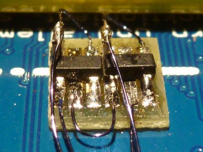
I built it very small using 1mm pitch contact strip, MOSFETs with SOT-23 footprint and 0805 resistors vertically on the gate contacts (see picture). You should be able to use logic-level MOSFETs in bigger packages, as long as the p-channel MOSFET is able to carry the maximal current of about 500mA (almost all can, but for example not the somewhat popular BS250). The resistor values are not critical, anything between 10k and 100k should do. Values lower than 10k will work, but draw more current when the LED power is turned on.


