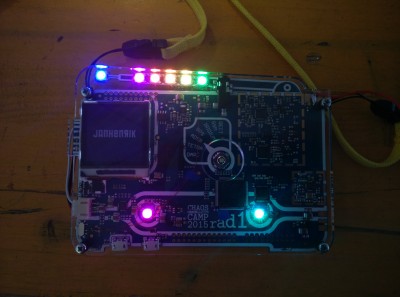
How to properly solder the LED's
To solder the LED's properly you have to do a few things. There are mainly two things you have to care of, the wiring and the capacitors. So we will add some thin wires, capacitors and of course the LED's to the rad1o.
Why?
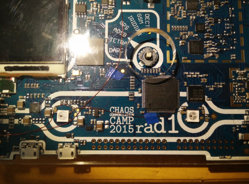
Wires: If you solder bridges onto the transistor pads (as explained earlier), the LEDs will be supplied with 3.3 V and not the recommended >4.5 V. With the wires there will be roughly 3.5 V to 4.3 V supplied to the LEDs, which is closer to their specification.
Capacitors: The WS2812B LED's are very vulnerable to not having a 100nF capacitor soldered next to their power pins, the internal controller pulses the LED's (PWM), so the current conversion is also very pulsed. That can cause voltage spikes on the ground (Yes, ground) line, which could destroy the controller/the LED.
LED's: Why do you ask? LED's are fancy \o/
What you will need:
- Thin isolated wire (0.2 mm enamelled copper wire [ Kupferlackdraht ] works fine)
- 8 100nF SMD capacitors
- 8 WS2812B LED's
- Soldering iron, solder, tweezers, Mate, etc
Step 1
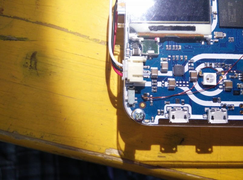
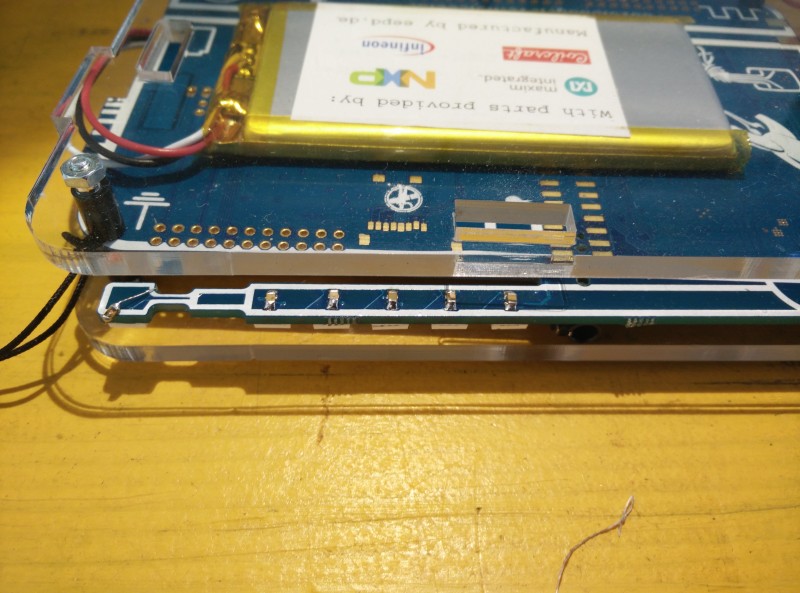
Add the thin wire to the solder pads like in the picture below.
Step 2
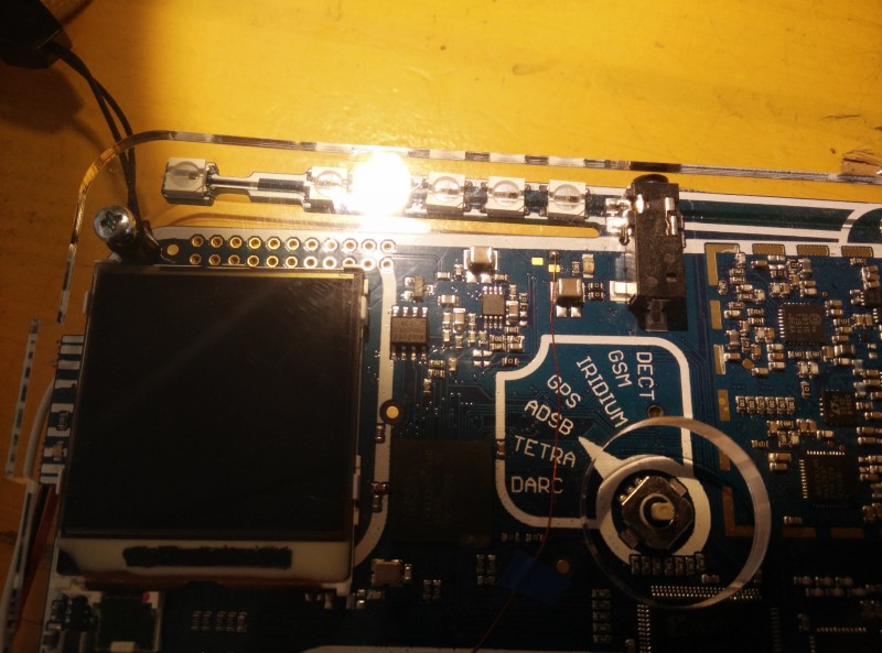
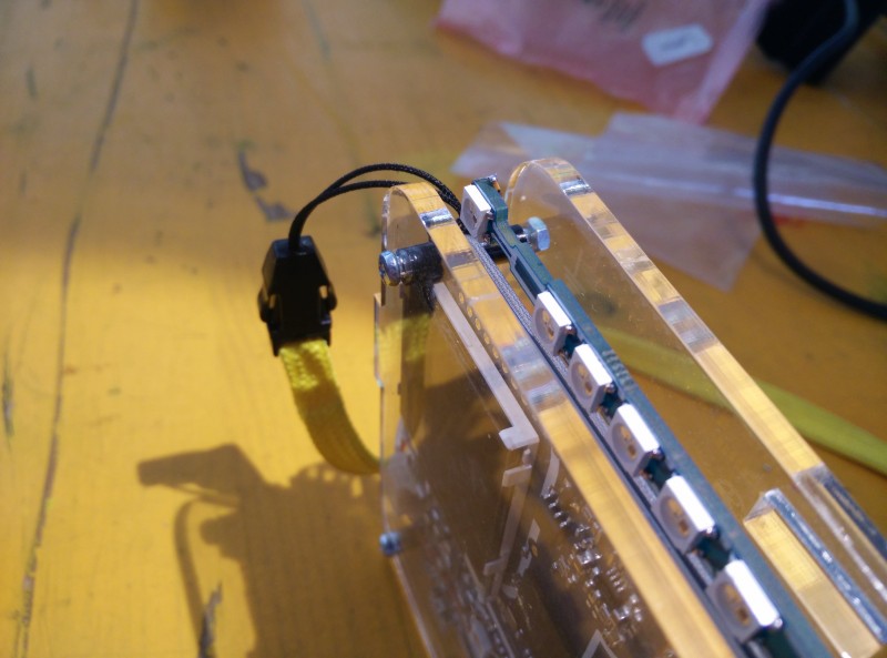
Add the LED's.
( scroll up for an explaining picture [ Or click me ] )
Step 3
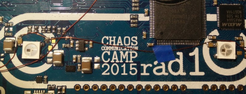
Now you should add the capacitors, that is kind of hard to do, because three capacitors don't have solder pads.
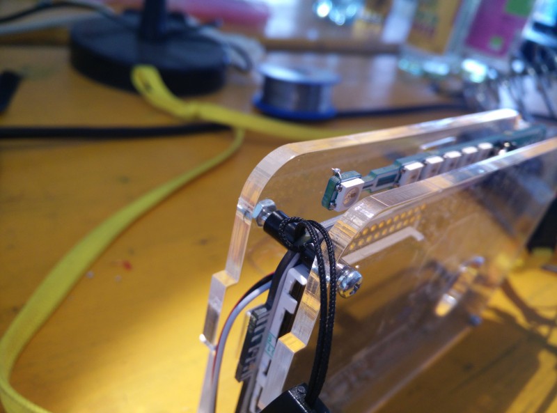
You can see the new capacitors next to the upper left LED pins.
I hope that the pictures are clear enough, there has to be a 100nF capacitor next to the power pins of every LED.
Step 4
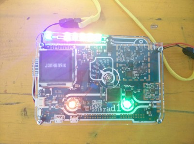
Test it.
Yay \o/

